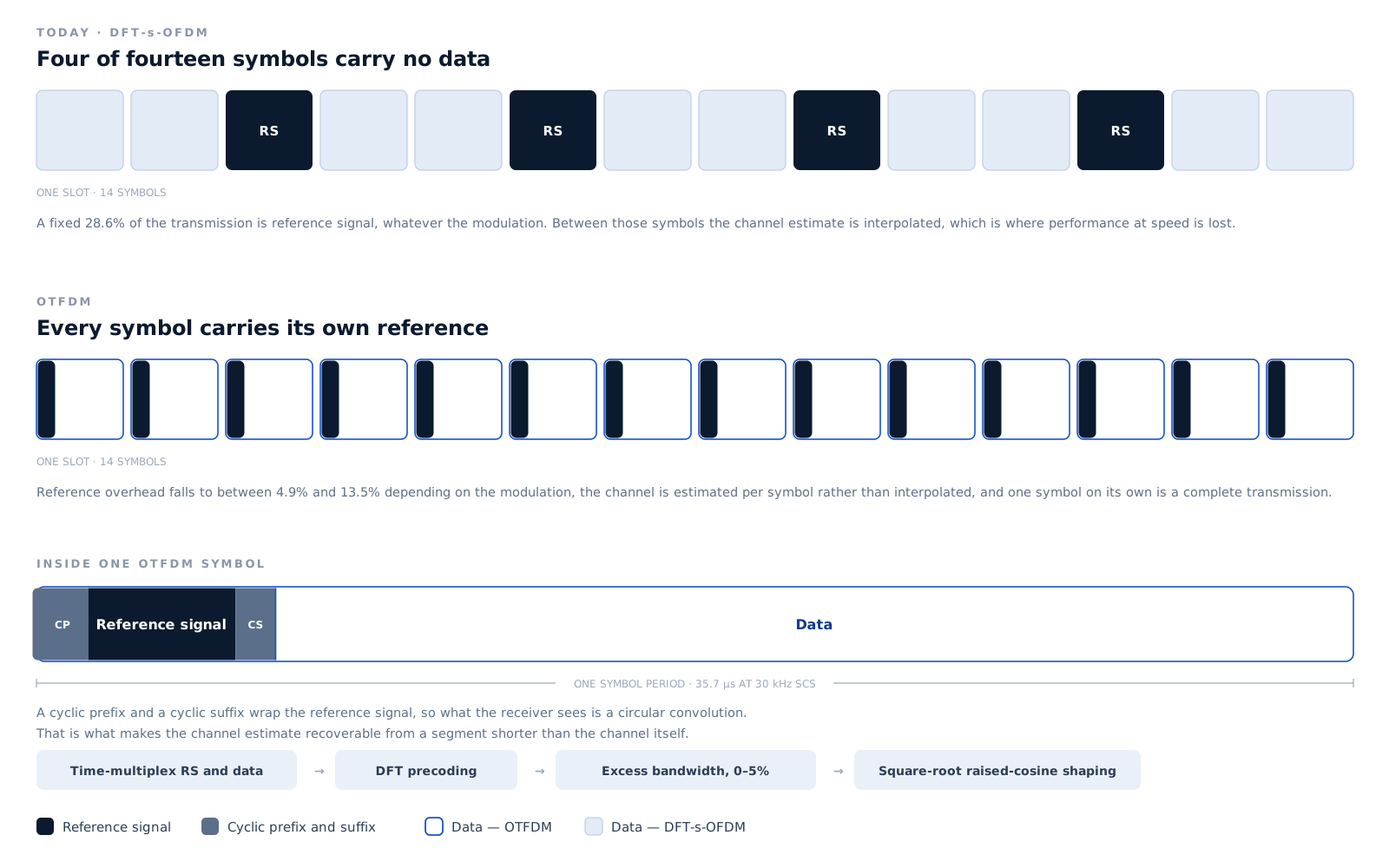
Orthogonal Time Frequency Multiplexing puts the reference signal and the data inside one symbol, separated in time and shaped in frequency. The symbol becomes a complete transmission on its own, which is what lets the overhead fall, the channel estimate stay current, and the latency collapse to a single symbol period.
5G NR uses DFT-s-OFDM on the uplink because it keeps the peak-to-average power ratio low, and a low ratio is what lets the amplifier in the device run close to saturation. Above 6 GHz, where amplifier efficiency falls away, that property matters more rather than less.
It arrives with two costs. The demodulation reference signal takes whole symbols of its own: a fixed 28.6% of the transmission, four symbols in every fourteen, whatever the modulation and whatever the channel actually needs.
And because the estimate is made on one symbol and then interpolated across the rest of the slot, it ages. At speed the channel has moved before the slot ends. That is why higher-order modulation becomes unusable at modest velocities, and why more reference symbols have to be inserted, paying the overhead twice.
Latency inherits the same structure. A transmission waits for a slot boundary and for a reference symbol, rather than going out when there is something to send.
OTFDM keeps the DFT precoding that gives DFT-s-OFDM its low peak-to-average behaviour, and changes where the reference signal sits.
Reference signal and data occupy one symbol, separated in the time domain. A cyclic prefix and a cyclic suffix wrap the reference segment, so the receiver sees a circular convolution and can recover the estimate from a segment shorter than the channel.
The precoded sequence is periodically extended and passed through a square-root raised-cosine filter. That bandwidth expansion, nothing for the lower-order modulations and 5% for 64-QAM and 256-QAM, suppresses the channel tails that would otherwise leak between the two segments.
The receiver folds the spectrum, extracts the reference samples, takes a least-squares estimate, windows and interpolates it across the allocation, and equalises with an MMSE filter. No interpolation across the slot, so no ageing.
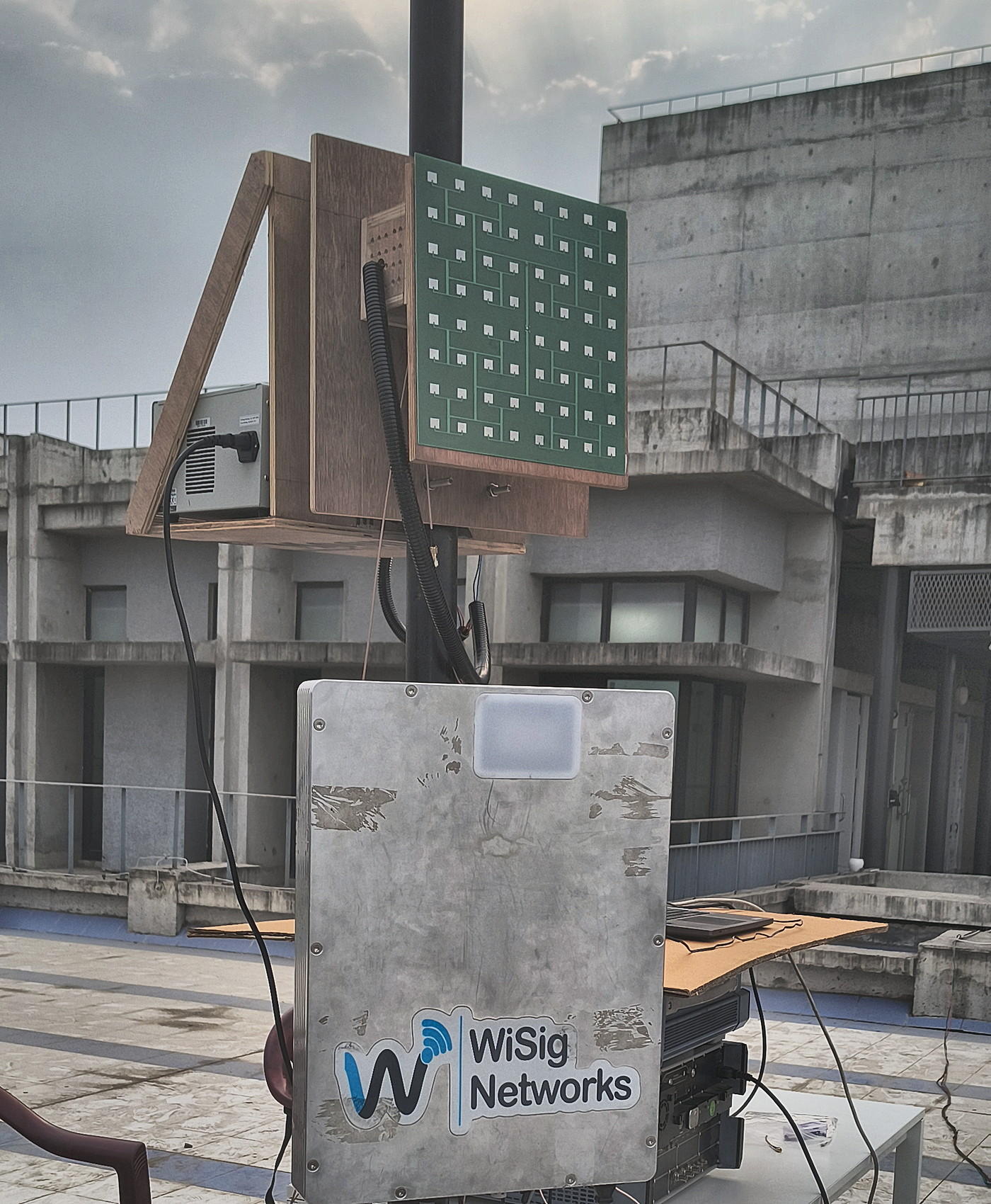
Simulation results from the two published papers, cited below. A 7 GHz carrier, 100 to 400 MHz of bandwidth and 30 to 120 kHz subcarrier spacing, the upper mid-band that 6G capacity is expected to come from.
| π/2-BPSK, QPSK and 16-QAM | Above 500 km/h |
|---|---|
| 64-QAM | 100 km/h at 30 kHz spacing · 300 km/h at 120 kHz |
| 256-QAM | 30 km/h at 30 kHz spacing · 100 km/h at 120 kHz |
| Every modulation, high-speed-train channel | 500 km/h, with additional reference of 1–2% of the allocation |
| Block error rate | Equivalent to DFT-s-OFDM across all five modulations |
| Peak-to-average power ratio | 0.13 to 0.21 dB better than DFT-s-OFDM at 1% CCDF, with 5% excess bandwidth |
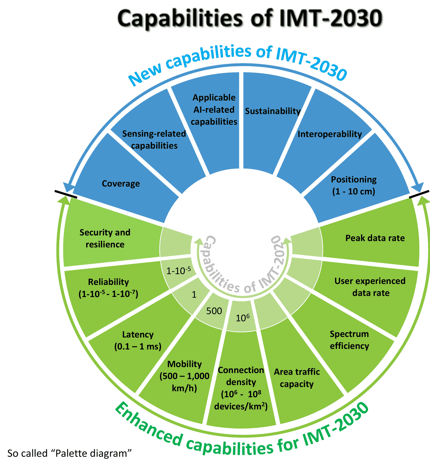
Capabilities of IMT-2030. Source: ITU-R Working Party 5D.
OTFDM was published as a waveform proposal for IMT-2030, the ITU framework 6G will be specified against. At 3GPP TSG RAN #108 in Prague in June 2025 the π/2-BPSK uplink waveform originated at IIT Hyderabad was extended for 6G; work on OTFDM and structural MIMO continues inside the approved 6G study item.
The IMT-2030 whitepaper pairs the two deliberately. OTFDM addresses latency and amplifier efficiency; structural MIMO addresses capacity, at up to 116 bits per second per hertz across all panels. Together the authors argue they meet the peak data rate, latency, spectrum efficiency and power efficiency targets in the ITU framework.
K. R. Gudimitla, S. A. Khan M and K. Kuchi.
Read the paper on arXivS. Bisoyi, M. M. Pasupuleti, K. Kuchi, K. Rao, H. Kumar, P. Reddy, S. Kumari and S. D. Amuru, July 2023.
Read the paper on arXiv
Operator trials, private 5G deployments, interoperability testing or academic collaboration.